Users Guide Client-Server Visualization: Difference between revisions
DaveDemarle (talk | contribs) (move tiled display to the large display chapter) |
|||
| Line 260: | Line 260: | ||
To use offscreen rendering in ParaView, give pvserver (or pvrenderserver) the --use-offscreen-rendering command-line option. Alternatively, set the PV_OFFSCREEN environment variable on the server to 1. On some systems, depending on the graphics hardware and drivers that are available, you may need to compile ParaView with Mesa support (for software rendering) and with the OSMESA library to enable offscreen rendering. | To use offscreen rendering in ParaView, give pvserver (or pvrenderserver) the --use-offscreen-rendering command-line option. Alternatively, set the PV_OFFSCREEN environment variable on the server to 1. On some systems, depending on the graphics hardware and drivers that are available, you may need to compile ParaView with Mesa support (for software rendering) and with the OSMESA library to enable offscreen rendering. | ||
Revision as of 20:02, 28 January 2011
Parallel ParaView
One of the main purposes of ParaView is to allow users to create visualizations of large data sets that reside on parallel systems without first collecting the data to a single machine. Transferring the data is often slow and wasteful of disk resources, and the visualization of large data sets can easily overwhelm the processing and memory resources of even high-performance workstations. This chapter describes the concepts behind the parallelism in ParaView and explains how a parallel visualization session can be initiated from within the ParaView user interface. Then two different modes of running ParaView in parallel are discussed: client / server mode, and client / data server / render server mode. The remainder of the chapter describes ParaView’s parallel rendering features (i.e., distributed rendering, offscreen rendering, and tiled displays).
Parallel Structure
ParaView has three main logical components: client, data server, and render server. When ParaView is started, the client is connected to what is called the builtin server; in this case all three components exist within the same process. Alternatively, you can run the server as an independent program and connect the client to it. In this case the server process contains both the data and render server components. The server can also be started as two separate programs: one for the data server and one for the render server. The server programs are data-parallel programs that can be run as a set of independent processes running on different CPUs. The processes use MPI to coordinate their activities as each works on different pieces of the data.
The client is responsible for the user interface of the application. ParaView’s general-purpose client was written to make powerful visualization and analysis capabilities available from an easy-to-use interface. The client component is a serial program that controls the server components through the Server Manager API. See chapter Error: Reference source not found for a discussion of the Server Manager.
The data server is primarily constructed from VTK readers, sources, and filters. It is responsible for reading and/or generating data, processing it, and producing geometric models that the render server and client will display. The data server exploits data parallelism by partitioning the data, adding ghost levels around the partitions as needed, and running synchronous parallel filters. Each data server process has an identical VTK pipeline, and each process is told which partition of the data it should load and process.
The render server is responsible for rendering the geometry. Like the data server, the render server can be run in parallel and has identical visualization pipelines (only the rendering portion of the pipeline) in all of its processes. Having the ability to run the render server separately from the data server allows for an optimal division of labor between computing platforms. Most large computing clusters are primarily used for batch simulations and do not have hardware rendering resources. Since it is not desirable to move large data files to a separate visualization system, the data server can run on the same cluster that ran the original simulation. The render server can be run on a separate visualization cluster that has hardware rendering resources.
It is possible to run the render server with fewer processes than the data server but never more. Visualization clusters typically have fewer nodes than batch simulation clusters, and processed geometry is usually significantly smaller than the original simulation dump. ParaView repartitions the geometric models on the data server before they are sent to the render server.
Although ParaView is designed from the ground up to be a parallel application, by default ParaView is built without parallel support. This is because there are many different versions of MPI, the library ParaView’s servers use internally for parallel communication. To use ParaView’s parallel processing features in the server, you must first compile ParaView with MPI support as described in section Error: Reference source not found.
Connecting the Client
You can establish connections between the independent programs that make up parallel ParaView from within the client’s user interface. The user interface even allows you to spawn the external programs and then automatically connect to them. Once you specify the information that ParaView needs to connect to, or spawn and connect to, the server components, ParaView saves it to make it easy to reuse the same server configuration at a later time.
The Choose Server dialog shown below is the starting point for making and using server configurations. The Connect entry on the ParaView client’s File menu brings it up. The dialog shows the servers that you have previously configured. To connect to a server, click its name to select it; then click the Connect button at the bottom of the dialog box. To make changes to settings for a server, select it, and click Edit Server. To remove a server from the list, select it, and click Delete Server.

To configure a new server connection, click the Add Server button to add it to the list. The dialog box shown below will appear. Enter a name in the first text entry box; this is the name that will appear in the Choose Server dialog (shown above).

Next select the type of connection you wish to establish from the Server Type menu. The possibilities are as follows. The “reverse connection” entries mean that the server connects to the client instead of the client connecting to the server. This may be necessary when the server is behind a firewall. Servers are usually run with multiple processes and on a machine other than where the client is running.
- Client / Server: Attach the ParaView client to a server.
- Client / Server (reverse connection): Connect a server to the ParaView client.
- Client / Data Server / Render Server: Attach the ParaView client to separate data and render servers.
- Client / Data Server / Render Server (reverse connection): Attach both a data and a render server to the ParaView client.
In either of the client / server modes, you must specify the name or IP address of the host machine (node 0) for the server. You may also enter a port number to use, or you may use the default (11111). If you are running in client / data server / render server mode, you must specify one host machine for the data server and another for the render server. You will also need two port numbers. The default one for the data server is 11111; the default for the render server is 22221.
When all of these values have been set, click the Configure button at the bottom of the dialog. This will cause the Configure Server dialog box, shown below, to appear. You must first specify the startup type. The options are Command and Manual. Choose Manual to connect to a server that has been started or will be started externally, on the command line for instance, outside of the ParaView user interface. After selecting Manual, click the Save button at the bottom of the dialog.

If you choose the Command option, in the text window labeled Execute an external command to start the server:, you must give the command(s) and any arguments for starting the server. This includes commands to execute a command on a remote machine (e.g., ssh) and to run the server in parallel (e.g., mpirun). You may also specify an amount of time to wait after executing the startup command(s) and before making the connection between the client and the server(s). (See the spin box at the bottom of the dialog.) When you have finished, click the Save button at the bottom of the dialog.
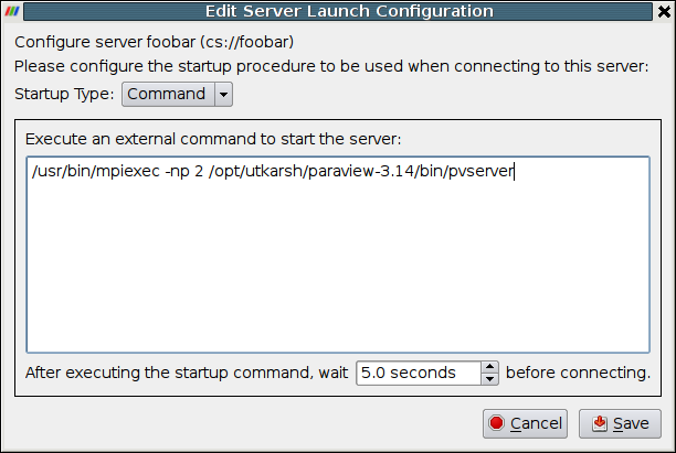
Clicking the Save button in the Configure Server dialog will return you to the Choose Server dialog (shown earlier in this section). The server you just configured will now be in the list of servers you may choose. Thereafter, whenever you run ParaView you can connect to any of the servers that you have configured. You can also give the ParaView client the –-server=server_config_name command-line argument to make it automatically connect to any of the servers from the list when it starts.
You can save and/or load server configurations to and/or from a file using the Save Servers and Load Servers buttons, respectively, on the Choose Server dialog. The format of the XML file for saving the server configurations is discussed online (http://paraview.org/Wiki/Server_Configuration).
Client / Server Mode
As mentioned in the introduction to this chapter, it is often useful to visualize data that physically resides on a computer other than the one driving the visualization. Instead of copying the data to the local workstation, a ParaView server can be run on the remote computer(s), and a ParaView client can be run on the local workstation. The two programs communicate to create a single ParaView session. The server loads and processes the data, and the client creates and displays the graphical user interface that allows the user to interact with the data.
Client / Server Mode refers to a parallel ParaView session in which data server and render server components reside within the same set of processes, and the client is completely separate. The pvserver executable combines the two server components into one process.
You can run pvserver as a serial process on a single machine. If ParaView was compiled with parallel support, you can also run it as an MPI parallel program on a group of machines. Instructions for starting a program with MPI are implementation- and system-dependent, so contact your system administrator for information about starting an application with MPI. With the MPICH implementation of MPI, the command to start the server in parallel usually follows the format shown here.
mpirun –np <number_of_processes> pvserver <pvserver’s arguments>
By default, pvserver will start and then wait for the client to connect to it. To make the connection, select Connection from the File menu, select (or make and then select) a configuration for the server (described in section 1.2), and click Connect. Note that you must start the server before the client attempts to connect to it.
If the computer running the server is behind a firewall, it is useful to have the server initiate the connection instead of the client. The ‑-reverse-connection (or -rc) command-line option tells the server to do this. The server must know the name of the machine to which it should connect; this is specified with the --client-host (or -ch) argument. Note that when the connection is reversed, you must start the client and instruct it to wait for a connection before the server attempts to connect to it.
The client-to-server connection is made over TCP, using a default port of 11111. If your firewall puts restrictions on TCP ports, you may want to choose a different port number. In the client dialog, simply choose a port number in the Port entry of the Configure New Server dialog. Meanwhile, give pvserver the same port number by including --server-port (or –sp)in its command-line argument list.
An example command line to start the server and have it initiate the connection to a particular client on a particular port number is given below.
pvserver –rc –ch=magrathea –sp=26623
Render Server
The render server allows you to designate a separate group of machines (i.e., apart from the data server and the client) to perform rendering. This parallel mode lets you use dedicated rendering machines for parallel rendering rather than relying on the data server machines, which may have limited or no rendering capabilities. In ParaView, the number of machines (N) composing the render server must be no more than the number (M) composing the data server.
There are two sets of connections that must be made for ParaView to run in render-server mode. The first connection set is between the client and the first node of each of the data and render servers. The second connection set is between the nodes of the render server and the first N nodes of the data server. Once all of these connections are established, they are bi-directional. The diagram in Figure 5 depicts the connections established when ParaView is running in render server mode. Each double-ended arrow indicates a bi-directional TCP connection between pairs of machines. The dashed lines represent MPI connections between all machines within a server. In all the diagrams in this section, the render server nodes are denoted by RS 0, RS 1, …, RS N. The data server nodes are similarly denoted by DS 0, DS 1, …, DS N, …, DS M.

The establishment of connections between client and servers can either be forward (from client to servers) or reverse (from servers back to client). Likewise, the connections between render server and data server nodes can be established either from the data server to the render server or from the render server to the data server.
The main reason for reversing the direction of any of the initial connections is that machines behind firewalls are able to initiate connections to machines outside the firewall, but not vice versa. If the data server is behind a firewall, the data server should initiate the connection with the client, and the data server nodes should connect to the render server nodes. If the render server is behind the firewall instead, both servers should initiate connections to the client, but now the render server nodes should initiate the connections with the nodes of the data server.
In the remaining diagrams in this section, each arrow indicates the direction in which the connection is initially established. Double-ended arrows indicate bi-directional connections that have already been established. In the example command lines, optional arguments are enclosed in []’s. The rest of this section will be devoted to discussing the two connections required for running ParaView in render server mode.
Connection 1: Connecting the client and servers
The first connection that must be established is between the client and the first node of both the data and render servers. By default, the client initiates the connection to each server, as shown in Figure 6. In this case, both the data server and the render server must be running before the client attempts to connect to them.

To establish the connections shown above, do the following. First, from the command line of the machine that will run the data server, enter “pvdataserver” to start it. Next, from the command line of the machine that will run the render server, enter “pvrenderserver” to start the render server. Now, from the machine that will run the client, start the client application, and connect to the running servers, as described in section 1.2 and summarized below.
Start ParaView and select Connect from the File menu to open the Choose Server dialog. Select Add Server to open the Configure New Server dialog. Create a new server connection with a Server Type of Client / Data Server / Render Server. Enter the machine names or IP addresses of the server machines in the Host entries. Select Configure, and then in the Configure Server dialog, choose Manual. Save the server configuration, and Connect to it. At this point ParaView will establish the two connections. This is similar to running ParaView in client/server mode but with the addition of a render server.
The connection between the client and the servers can also be initiated by the servers. As explained above, this is useful when the servers are running on machines behind a firewall. In this case, the client must be waiting for both servers when they start. The diagram indicating the initial connections is shown in Figure 7.

To establish the connections shown above, start by opening the Configure New Server dialog on the client. Choose Client / Data Server / Render Server (reverse connection) for the Server Type in the Configure New Server dialog. Next, add both --reverse-connection (or -rc) and --client-host (or -ch) to the command lines for the data server and render server. The value of the --client-host parameter is the name or IP address of the machine running the client. You can use the default port numbers for these connections, or you can specify ports in the client dialog by adding the --data-server-port (or –dsp) and --render-server-port (or –rsp) command-line arguments to the data server and render server command lines, respectively. The port numbers for each server must agree with the corresponding Port entries in the dialog, and they must be different from each other.
For the remainder of this chapter, -rc will be used instead of --reverse-connection when the connection between the client and the servers is to be reversed.
Connection 2: Connecting the render and data servers
After the connections are made between the client and the two servers, the servers will establish connections with each other. In parallel runs, this server-to-server connection is a set of connections between all N nodes of the render server and the first N nodes of the data server. By default the data server initiates the connection to the render server, but this can be changed with a configuration file. The format of this file is described below.
The server that initiates the connection must know the name of the machine running the other server and the port number it is using. In parallel runs, each node of the connecting server must know the name of the machine for the corresponding process in the other server to which it should connect. The port numbers are randomly assigned, but they can be assigned in the configuration file as described below.
The default set of connections is illustrated in Figure 8. To establish these connections, you must give the data server the connection information discussed above, which you specify within a configuration file. Use the --machines (or –m) command line argument to tell the data server the name of the configuration file. In practice, the same file should be given to all three ParaView components. This ensures that the client, the render server, and the data server all agree on the network parameters.
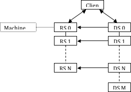
An example network configuration file, called machines.pvx in this case, is given below.
<?xml version="1.0" ?>
<pvx>
<Process Type="client">
</Process>
<Process Type="render-server">
<Option Name="render-node-port" Value="1357"/>
<Machine Name="rs_m1"
Environment="DISPLAY=rs_m1:0"/>
<Machine Name="rs_m2"
Environment="DISPLAY=rs_m2:0"/>
...
</Process>
<Process Host="data-server">
<Machine Name="ds_m1" />
<Machine Name="ds_m2" />
<Machine Name="ds_m3" />
<Machine Name="ds_m4" />
</Process>
</pvx>
Sample command-line arguments that use the configuration file above to initiate the network illustrated in Figure 8 are given below.
mpirun –np 2 pvdataserver –m=machines.pvx
mpirun –np 2 pvrenderserver -m=machines.pvx
paraview –m=machines.pvx
It should be noted that the machine configuration file discussed here is a distinct entity from, and has a different syntax from, the server configuration file discussed at the end of section 1.2. That file is read only by the client; the file discussed here will be given to the client and both servers.
In the machines file above, the render-node-port entry in the render server’s XML element tells the render server the port number on which it should listen for a connection from the data server, and it tells the data server what port number it should attempt to contact. This entry is optional, and if it does not appear in the file the port number will be chosen automatically. Note that it is not possible to assign port numbers to individual machines within the server; all will be given the same port number or use the automatically chosen one. Note also that each render server machine is given a display environment variable in this file. This is not required to establish the connections, but it is helpful if you need to assign particular X11 display names to the various render server nodes.
The initial connection between the nodes of the two servers is made from the data server to the render server. You can reverse this such that the render server nodes connect to the corresponding nodes of the data server instead as shown in Figure 9.
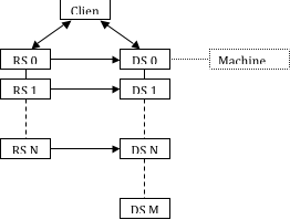
Typically when the server connection is reversed, the direction of the connection between the client and the servers is also reversed (e.g., if the render server is behind a firewall). In this case, the render server must have the machine names and a connection port number to connect to the data server. The same XML file is used for this arrangement as with the standard connection. The only difference in this case is that the render-node-port entry, if it is used, must appear in the data server’s XML element instead of the render server’s element. Example command-line arguments to initiate this type of network are given here.
paraview –m=machines.pvx
mpirun –np <M> pvdataserver –m=machines.pvx -rc -ch=client
mpirun –np <N> pvrenderserver –m=machines.pvx -rc -ch=client
Parallel Rendering / Compositing
ParaView’s server performs all data-processing tasks. This includes generation of a polygonal representation of the full data set and of decimated LOD models. Rendering, however, can occur either on the server or on the client depending on which is most efficient.
In many cases, the polygonal representation of the data set is much smaller than the original data set. (In an extreme case, a simple outline may be used to represent a very large structured mesh.) In these cases, it may be better to transmit the polygonal representation from the server to the client, and then let the client render it. The client can render the data repeatedly, when the viewpoint is changed for instance, without causing additional network traffic. Only when the data changes will network traffic occur. If the client workstation has high-performance rendering hardware, it can sometimes render even large data sets interactively in this way.
The second option is to have each node of the server render its geometry and send the resulting images to the client for display. There is a penalty per rendered frame for compositing images and sending the image across the network. However, ParaView’s image compositing and delivery is very fast, and there are many options to ensure interactive rendering in this mode. Therefore, although small models may be collected and rendered on the client interactively, ParaView’s distributed rendering can render models of all sizes interactively.
ParaView automatically chooses a rendering strategy to achieve the best rendering performance. You can control the rendering strategy explicitly, forcing rendering to occur entirely on the server or entirely on the client for example, by choosing Settings… from the Edit menu of ParaView. Double click on Render View from the window on the left-hand side of the Options dialog, and then click on Server. The rendering strategy parameters shown in Figure 10 will now be visible.
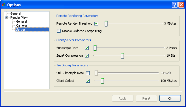
Remote Render Threshold: This slider determines how large the data set must be in order for parallel rendering with image compositing and delivery to be used (as opposed to collecting the geometry to the client). The value of this slider is measured in megabytes. Only when the entire data set consumes more memory than this value will compositing of images occur. If the check box beside the Remote Render Threshold slider is unmarked, then compositing will not happen; the geometry will always be collected. This is only a reasonable option when you can be sure the data set you are using is very small. In general, it is safer to move the slider to the right than to uncheck the box.
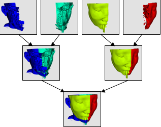
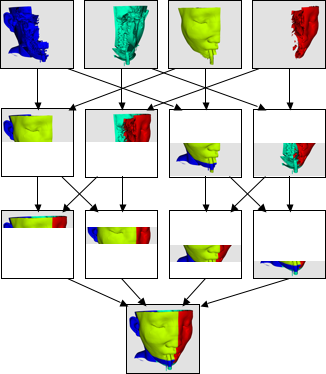
ParaView uses IceT to perform image compositing. IceT is a parallel rendering library that takes multiple images rendered from different portions of the geometry and combines them into a single image. IceT employs several image-compositing algorithms, all of which are designed to work well on distributed memory machines. Examples of two such image-compositing algorithms are depicted in Figure 11 and Figure 12. IceT will automatically choose a compositing algorithm based on the current workload and available computing resources.
Disable Ordered Compositing: By default, depth information is used to composite images together. As part of its normal operation, graphics hardware keeps a depth buffer containing the relative depth of each pixel from the camera. For compositing, this depth buffer is retrieved and used to choose which version of the pixel is closest to the camera.
Choosing the closest pixel color is fine when the original geometry is opaque, but when the original geometry comprises transparent polygons or volumes, this compositing operation produces incorrect results. For proper compositing of translucent geometry, the colors must be blended in front to back order. When the Disable Ordered Compositing flag is off, IceT will composite the images in this order.
In general, a collection of polygons or polyhedra has no true front-to-back order. When Disable Ordered Compositing is off, ParaView will redistribute the data to ensure a proper visibility order. The distribution remains fixed during viewpoint manipulations, but it needs to be recomputed whenever a parameter of a filter changes, causing the data to change. Because redistribution is a potentially lengthy operation, you may want to turn Disable Ordered Compositing on if you are not rendering any translucent objects. This can sometimes speed up the parallel rendering process.
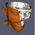
Subsample Rate: The time it takes to composite and deliver images is directly proportional to the size of the images. The overhead of parallel rendering can be reduced by simply reducing the size of the images. ParaView has the ability to subsample images before they are composited and inflate them after they have been composited. The Subsample Rate slider specifies the amount by which images are subsampled. This is measured in pixels, and the subsampling is the same in both the horizontal and vertical directions. Thus a subsample rate of 2 will result in an image that is ¼ the size of the original image. The image is scaled to full size before it is displayed on the user interface, so the higher the subsample rate, the more obviously pixilated the image will be during interaction as demonstrated in Figure 13. When the user is not interacting with the data, no subsampling will be used. If you want subsampling to always be off, unmark the check box beside the Subsample Rate slider.
 |
|
|
| No Subsampling | Subsample Rate: 2 pixels | Subsample Rate: 8 pixels |
Figure 13. The effect of subsampling on image quality
Squirt Compression: When ParaView is run in client/server mode, ParaView uses image compression to optimize the image transfer. The compression uses an encoding algorithm optimized for images called SQUIRT (developed at Sandia National Laboratories).
SQUIRT uses simple run-length encoding for its compression. A run-length image encoder will find sequences of pixels that are all the same color and encode them as a single run length (the count of pixels repeated) and the color value. ParaView represents colors as 24-bit values, but SQUIRT will optionally apply a bit mask to the colors before comparing them. Although information is lost when this mask is applied, the sizes of the run lengths are increased, and the compression gets better. The bit masks used by SQUIRT are carefully chosen to match the color sensitivity of the human visual system. A 19-bit mask employed by SQUIRT greatly improves compression with little or no noticeable image artifacts. Reducing the number of bits further can improve compression even more, but it can lead to more noticeable color-banding artifacts.
The Squirt Compression slider determines the bit mask used during interactive rendering (i.e., rendering that occurs while the user is changing the camera position or otherwise interacting with the data). During still rendering (when the user is not interacting with the data), lossless compression is always used. The check box to the left of the Squirt Compression slider toggles whether the SQUIRT compression algorithm is used at all.
The options in the Tile Display Parameters portion of the dialog are discussed in section 1.7.
Offscreen Rendering
When running ParaView in a parallel mode, it may be helpful for the remote rendering processes to do their rendering in offscreen buffers. For example, other windows may be displayed on the node(s) where you are rendering; if these windows cover part of the rendering window, they may be captured as part of the display results from that node. A similar situation could occur if more than one rendering process is assigned to a single machine, and the processes share a display. Also, in some cases the remote rendering nodes are not directly connected to a display.
To use offscreen rendering in ParaView, give pvserver (or pvrenderserver) the --use-offscreen-rendering command-line option. Alternatively, set the PV_OFFSCREEN environment variable on the server to 1. On some systems, depending on the graphics hardware and drivers that are available, you may need to compile ParaView with Mesa support (for software rendering) and with the OSMESA library to enable offscreen rendering.