TubeTK/Documentation/InteractivePDFSegmenter
From KitwarePublic
< TubeTK | Documentation
Jump to navigationJump to search
Revision as of 18:25, 26 July 2013 by Jamie.snape (talk | contribs)
Overview
The interactive PDF segmenter performs image segmentation based on a rough initial segmentation provided by the user. This initial segmentation can be "painted" by the user within 3D Slicer, and can be refined iteratively after visualizing the segmentation results.
The segmentation steps proceed as follows:
- Using the intensity statistics within the rough initial segmentation, calculate the class probabilities for each pixel in the image to be segmented
- Smooth the probability map
- Classify each pixel to the class with the highest probability: now every pixel has a label
- Analyze connected components relative to the rough initial segmentation: retain only those classified pixels that are connected to a pixel of the same class in the rough initial segmentation
- Perform hole-filling on the label map
- Perform erosion on the label map
- Perform connected components analysis again: should now have well connected regions
- Perform dilation on the label map
Running the Interactive PDF Segmenter
The interactive PDF segmenter is to be used with 3D Slicer (see the TubeTK with Slicer page for setup instructions).
Its implementation can be found in TubeTK/Applications/SlicerModules/InteractivePDFSegmenter.py.
Parameters
- Input Volume 1: The image to be segmented
- Input Volumes 2 and 3 (optional): Optional images visualizing the same structures as the image to be segmented. Input volumes 1,2 and 3 must be co-registered. If input volumes 2 and 3 are provided, intensity statistics are calculated in a multi-dimensional space by considering the intensities in all of the input volumes.
- Output Volume: The segmentation results (label map)
- Label Map: The rough initial segmentation provided as input to the algorithm
- Void Id: Value that specifies nothing in the label map (typically 0)
- Erosion Radius: Dictates the strength of the erosion performed in step 5 above
- Hole Fill Iterations: Dictates the number of hole-filling iterations performed in step 4 above
- Probability Smoothing Standard Deviations: Dictates the strength of the probability map smoothing in step 2 above
- Draft Mode: TODO
- Reclassify Object Mask: If true, the pixel classifications provided by the rough initial segmentation can be changed during the segmentation process. If false, the pixel classifications within the rough initial segmentation are fixed and will be retained in the final segmentation.
- Reclassify Not Object Mask: If true, the pixel classifications within the rough initial segmentation for the "Void Id" can be updated as part of step 3 above, based on the intensity statistics of the rough initial segmentation. If false, the "Void Id" classifications within the rough initial segmentations dictate a "no-go" zone and will be retained in the final segmentation.
Tutorial
Tutorial Data
- In this example, we will attempt to segment gray matter, white matter and cerebrospinal fluid (CSF)
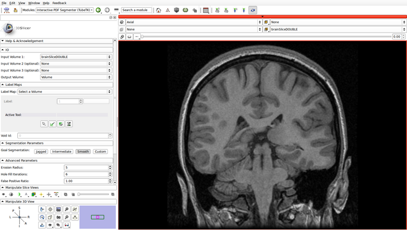
- The 2D brain image used in this example is distributed as part of Slicer4, and is located in Slicer4/Testing/Data/Input/brainSliceDOUBLE.mha
Tutorial Steps
- Load brainSliceDOUBLE.mha:
- File -> Add Volume
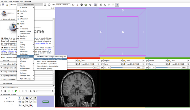
- Open the Interactive PDF Segmenter module
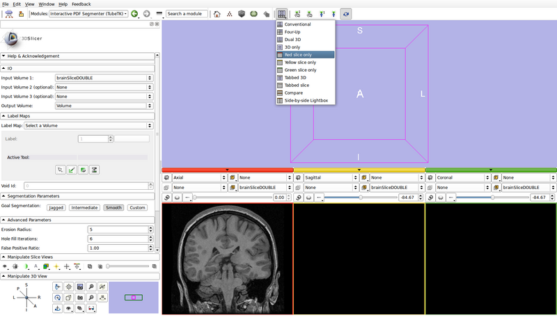
- Set the input and output volumes
- Input Volume 1: brainSliceDOUBLE
- Input Volume 2 (optional): None
- Input Volume 3 (optional): None
- Output Volume: Create new volume
- Creates a new volume called "Volume": this will hold the final segmentation
- Set the view layout to "Red slice only"
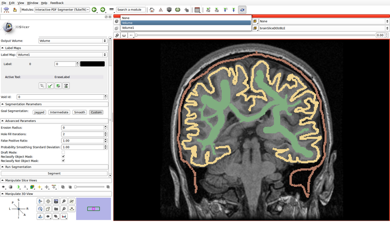
- Create the label map roughly outlining the structures to be segmented and the background
- Label Map: Create new volume
- Creates a new volume called "Volume1": this will hold the input label map
- A small version of Slicer's Editor module is embedded into the Interactive PDF Segmenter
- Create a label map roughly outlining the structures of interest and the background by using the paint, erase and threshold functions
- Click on the "Paint" button to begin editing
- Use a different label color for each structure of interest: choose the label by clicking the colored push button
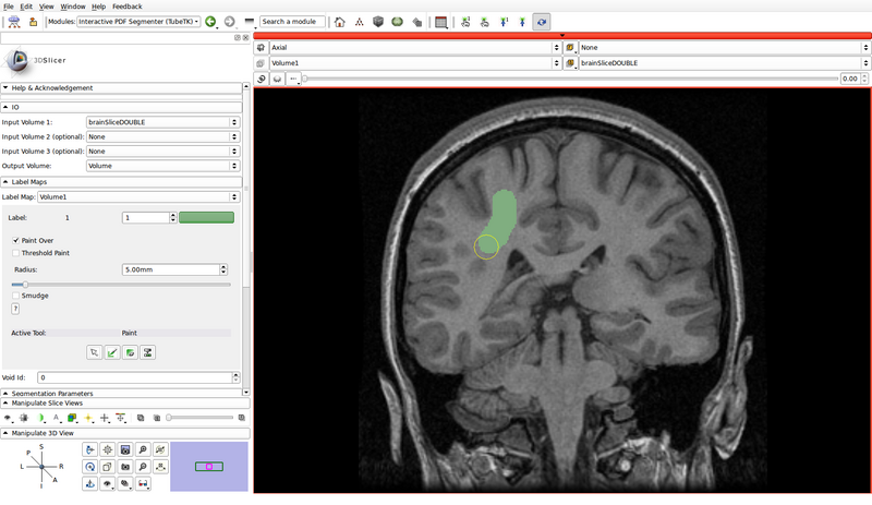
- Create a label for the background as well
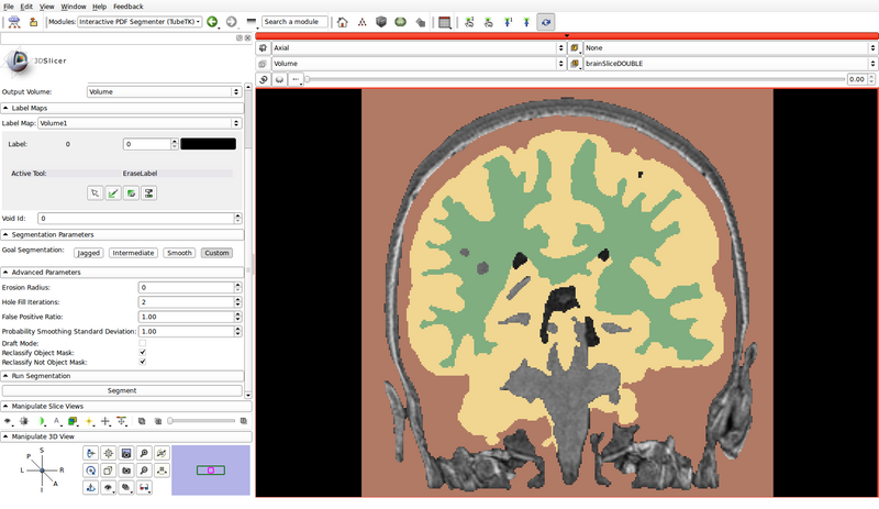
- In the following example, green represents gray matter, yellow represents white matter, and brown represents the cerebrospinal fluid (CSF):
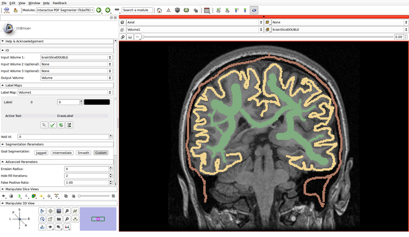
- Void Id: 0
- Label Map: Create new volume
- Specify the segmentation parameters
- The goal segmentation buttons provide example parameters depending on whether the shapes of the expected segmentations are jagged, smooth or intermediate
- In this example, we will use custom parameters
- Erosion Radius: 0
- Hole Fill Iterations: 2
- False Positive Ratio: 1.00
- Probability Smoothing Standard Deviation: 1.00
- Draft Mode: Off
- Reclassify Object Mask: On
- Reclassify Not Object Mask: On
- Run the segmentation
